5G RRU Heat Sink: End-to-End Delivery from Die-Cast Blank to EMC-Ready Assembly
A European telecom OEM needed a 5G RRU heat sink that had to pass six verification gates: thermal conductivity, salt-spray corrosion, EMC shielding, IP67 sealing, dimensional accuracy for power-amplifier contact, and cost. In a typical supply chain, this means five different factories, five handoffs, and five chances for something to go wrong. VOXEL delivered the full chain — from tooling to final assembly validation — as a single engineering program.
52 mm
Fin depth
0.86 mm
Fin thickness
60:1
Aspect ratio
180 W/m·K
Verified result
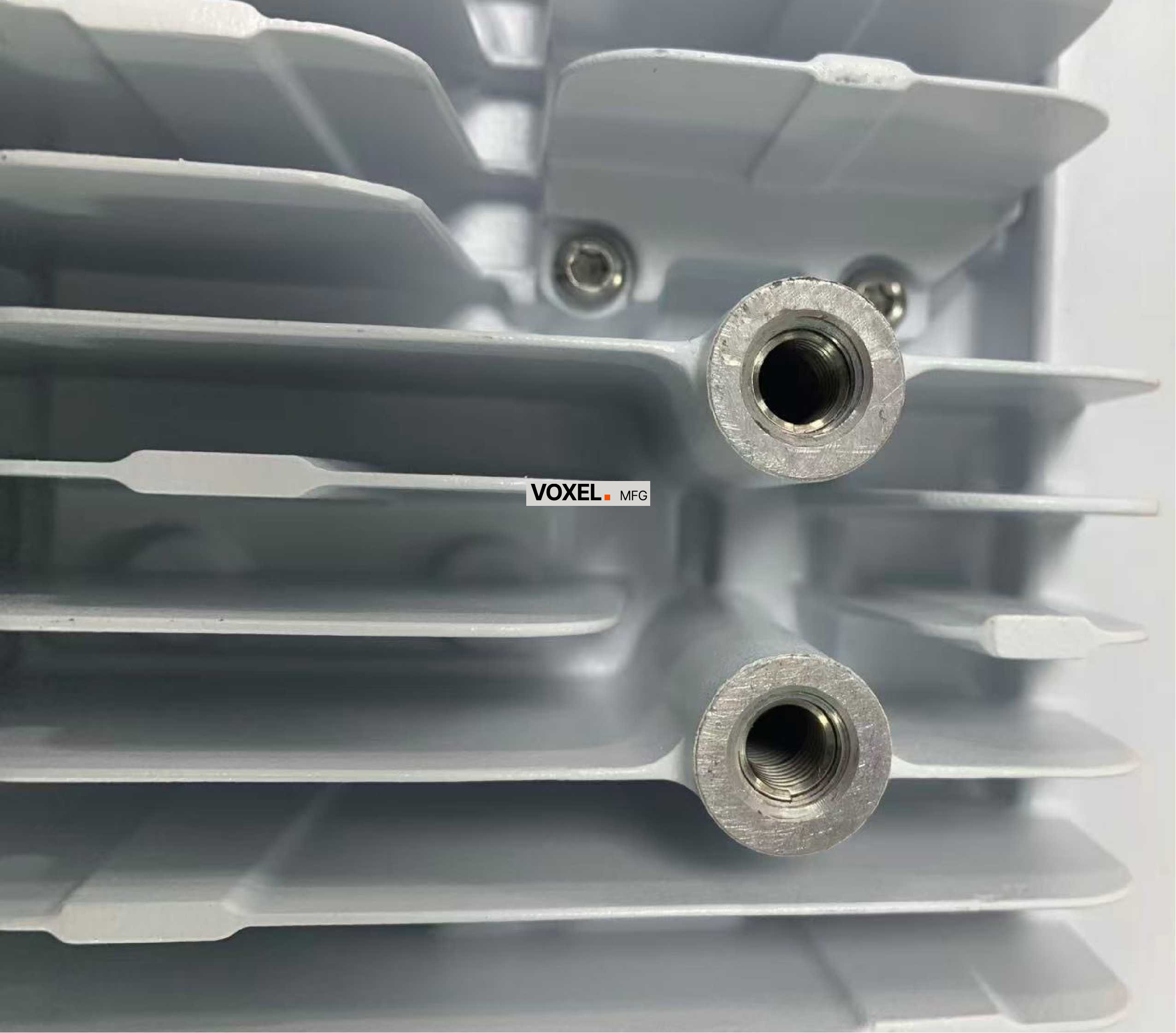
Finished 5G RRU heat sink with 370 mm x 260 mm footprint and extreme thin-wall fin geometry
The Industry Reality: How Complex a Heat Sink Delivery Chain Can Be
A 5G RRU heat sink from design to full system validation typically passes through five or six separate suppliers. Each handoff introduces risk: the mold designer may not understand the die-casting window; the die caster may not control surface quality for salt spray; the machinist may not protect fin geometry during clamping; the coating shop may not know the EMC shielding target. When something fails at final assembly, every supplier points to the previous one. The OEM is left holding the integration risk.
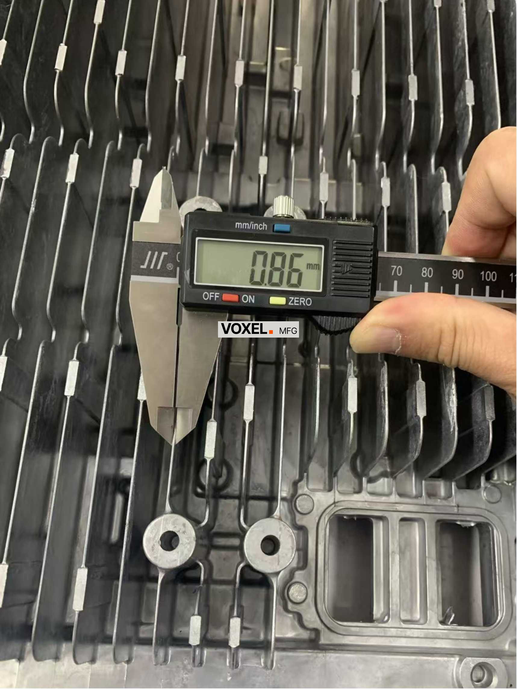
Fin measurement confirming the ultra-thin geometry required by the original design
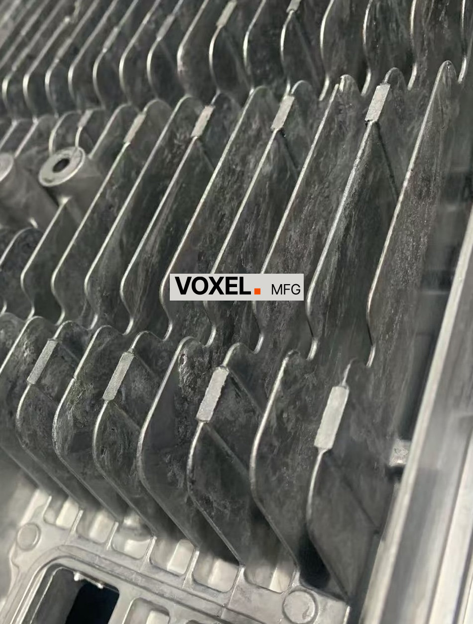
Initial trial result showing incomplete fill and porosity in the critical fin zone
The Problem: Four Hard Targets, One Part
A thermal design engineer at a telecom equipment manufacturer had run the simulations and secured internal approval. The spec sheet was clear:
| Target | Requirement | Why It Matters |
|---|---|---|
| Thermal conductivity | ≥ 170 W/m·K | Power amplifier heat dissipation |
| IP67 sealing | Zero porosity at fin base | Outdoor deployment, rain and dust proof |
| Salt-spray + color | Pass salt-spray test, match custom color card | Corrosion resistance + brand consistency |
| Material compliance | Copper ≤ 0.10% Wt, ROHS compliant | Tier-1 supply chain standard |
High-TC aluminum was the only path to the thermal target. But conventional die casting of 0.86 mm fins at 60:1 aspect ratio in high-TC alloy had low yield — the melt freezes faster in thin channels. And any porosity at the fin base would break IP67 sealing.
Their regular supplier ran trial shots. Short shots and gas porosity. The supplier's response was reasonable: thicken the fins to 1.2 mm to improve fill reliability. Under their standard process, that was the correct call.
But the client faced two more urgent problems. First, the project timeline was tight — telecom product launches are fixed, and a heat-sink redesign means re-simulation, re-tooling, and re-validation, blowing the schedule. Second, process risk was uncontrollable — the supplier lacked experience with high-TC aluminum thin-wall casting. Repeated trial failures had already burned valuable time. Continuing to iterate risked sand-hole defects, unacceptably low yield, and soaring per-part costs — eventually forcing the supplier to walk away, leaving the client to find a new partner under even more pressure. The client refused to thicken. Thickening meant derating the entire RRU — and in telecom, derating means re-certification, months of delay. More critically, porosity at the fin base would compromise IP67 sealing — not a cosmetic issue, but functional failure. A second supplier's independent assessment confirmed the same conclusion: the design exceeded their conventional process window. The client was facing a heat-sink redesign, a delayed product launch, and a difficult conversation with the operator.
Why It Was Hard: Four Constraints, Zero Margin for Compromise
The suppliers were not wrong. Under conventional die-casting conditions, 0.86 mm fins at a 60:1 aspect ratio would have unacceptably low yield. But the client's constraints were real and non-negotiable:
- Thermal performance: High-TC aluminum, targeting above 170 W/m·K — standard aluminum could not meet this
- Sealing density: Vacuum-grade porosity control for IP67 outdoor rating — any porosity meant sealing failure
- Salt-spray + custom color: Coating thickness must hit a narrow window — thick enough for corrosion resistance, thin enough to not interfere with EMC shielding continuity
- Material compliance: Copper ≤ 0.10% Wt — conventional high-TC alloys often run higher; this required alloy selection or formulation adjustment
High-TC aluminum transfers heat into the mold more aggressively, so the melt freezes sooner in thin channels. Meanwhile, any porosity at the fin base would compromise the sealed enclosure their outdoor deployment required. The factories were reading the process correctly — they just did not have the tools or the downstream process knowledge to operate outside their standard window.
Engineering Actions: Three Trials, Gradual Escalation
Conventional approaches end here. Engineering problem-solving begins. VOXEL kept the client's cooling geometry intact and widened the process window. Three trial iterations — the first two failed, and each failure narrowed the problem.
Trial 1: Standard process, confirm the boundary
Adopted standard gating layout and conventional die-casting parameters. Result: short shots at thin fin tips — the melt froze before reaching the deep end. Confirmed the problem: high-TC aluminum in 0.86 mm channels solidifies too fast. But was it a flow problem, a temperature problem, or both? Needed more data.
Trial 2: Gating redesign, narrow the problem
Redesigned gating with auxiliary flow features to increase fill velocity. Fill improved significantly, but gas porosity remained at the fin base — flow was sufficient, but gas trapped in the deep cavity could not escape. At this point we faced a choice: continue optimizing gating, or add vacuum equipment?
Analyzing short-shot data and gas distribution, we concluded: gating optimization alone could not solve deep-cavity venting — vacuum assistance was needed. Meanwhile, high-TC aluminum's fast solidification also required mold temperature compensation.
Material spectroscopy also revealed a second issue: the alloy's copper content was 0.14%, above the 0.10% spec limit. This meant alloy selection or formulation adjustment was needed alongside process changes.
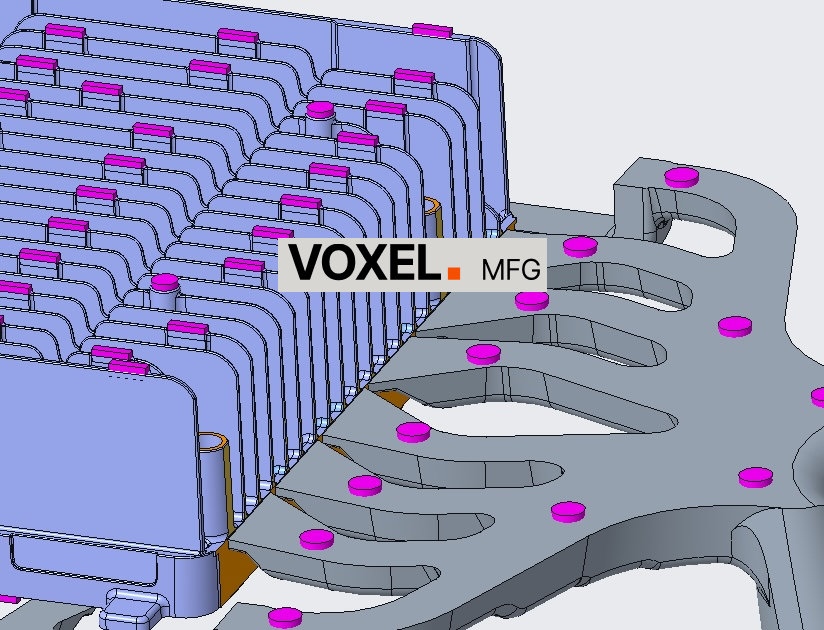
Original gating condition before the fill-speed correction
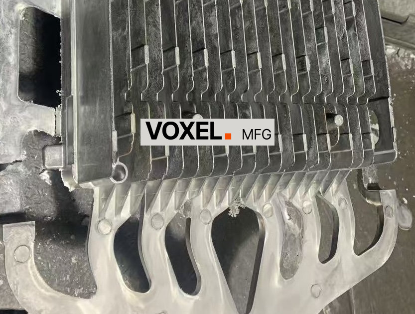
Updated gating strategy used to stabilize filling in the thin fin area
Trial 3: Vacuum + constant mold temp + alloy adjustment
Based on data from the first two trials, determined the mold temperature and vacuum parameter window. Combined updated gating with high-vacuum die casting and constant mold temperature control. Vacuum level controlled within the process window, effectively reducing trapped gas and back-pressure — critical for both complete fill and the sealed density required for IP67. Mold temperature maintained within the high-TC aluminum's fluidity range, compensating for its rapid solidification.
Worked with the material supplier to adjust alloy formulation, bringing copper content to 0.08% Wt.
Result: complete fill, controlled porosity. Visual inspection confirmed no surface porosity at the fin base, meeting IP67 sealing requirements. Thermal conductivity verified at 180 W/m·K. Material compliance passed.

Vacuum and mold-temperature control setup used to stabilize the thin-wall casting window
Key decision logic
Not "fully armed" with all equipment from the start, but based on data from the first two failures, gradually identified root causes, and finally decided which process measures were needed. This controlled trial costs and helped the client understand the value of each step.
Surface Treatment: Salt-Spray, Color Card, EMC — One Coating, Three Requirements
With the blank stable, the next challenge was the coating:
- Salt-spray resistance: Coating must pass stringent salt-spray testing for coastal deployment
- Custom color match: Client-specified color card, batch-to-batch consistency
- EMC shielding continuity: Coating thickness must not break the conductive path for EMC
This is where process knowledge from Tier-1 telecom supply chain matters. The heat sink sits between the upper and lower chambers of the RRU enclosure. Those two metal surfaces must make direct electrical contact to form a continuous shield — otherwise signals leak out and EMC fails. Powder coating on those mating surfaces acts as an electrical insulator. Too thick, and the metal-to-metal contact is broken — EMC fails even though salt-spray passes. Too thin, and corrosion protection is insufficient — salt-spray fails even though EMC passes. The coating thickness must hit a narrow window that satisfies both requirements simultaneously.
Pre-tested coating parameters before full production. Salt-spray passed — surface showed slight yellowing but no white spots, no blistering, no peeling, within the client's color card tolerance. Color matched. EMC pre-test passed.
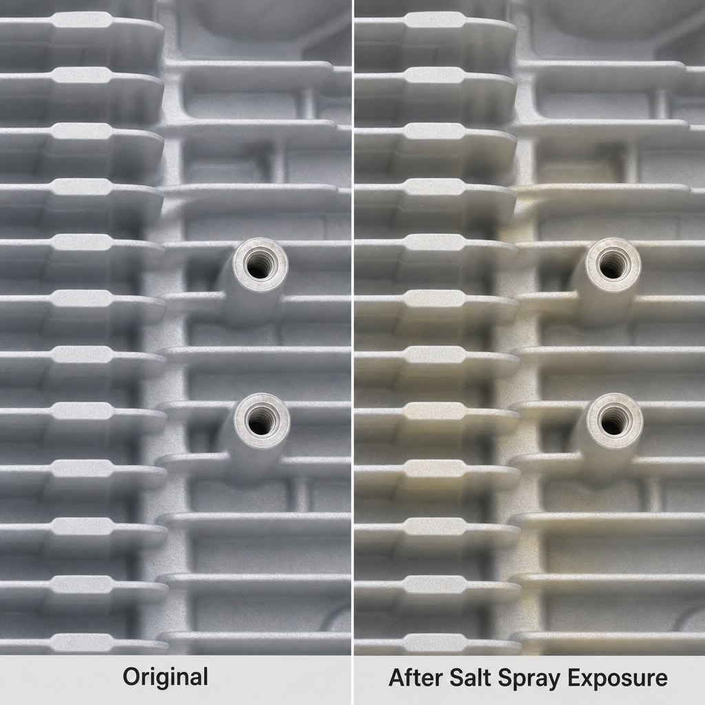
Salt-spray test comparison: original coating vs. post-test surface condition
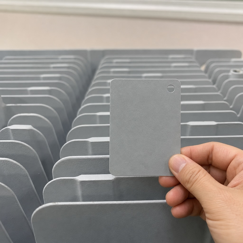
Color card matching and coating thickness control for salt-spray and EMC balance
Verification and Results: Four Targets Met, Design Preserved
The final process held the original fin geometry, eliminated the initial freeze-off behavior, and delivered a finished heat sink ready for telecom deployment. The alloy result was not just visually acceptable — it was measured and verified against the customer's requirements.
| Target | Requirement | Result | Verification |
|---|---|---|---|
| Thermal conductivity | ≥ 170 W/m·K | 180 W/m·K | Third-party material test |
| IP67 sealing | Zero porosity at fin base | Passed | Leak test |
| Salt-spray + color | Pass + match color card | Passed | Standard salt-spray test, color match |
| Material compliance | Copper ≤ 0.10% Wt | 0.08% Wt | Spectroscopy analysis |
- 52 mm deep fin geometry maintained without thickening the design
- 0.86 to 0.89 mm fin sections stabilized through gating and thermal control
- Three focused trial iterations converging on a stable production window
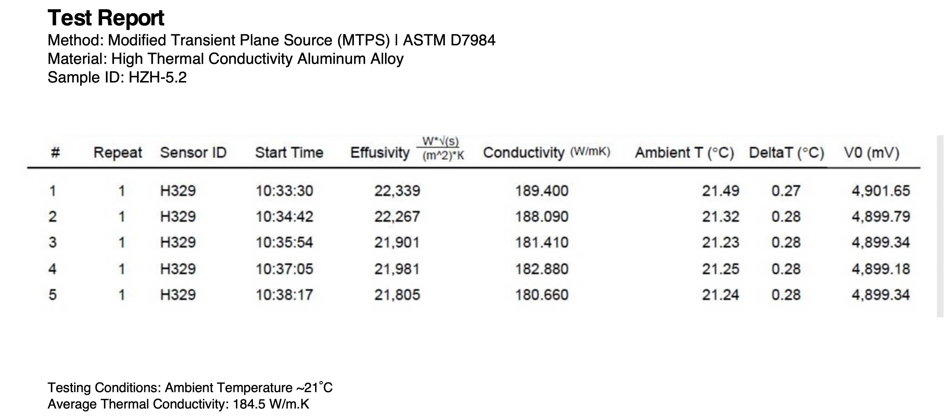
Test report confirming the final thermal conductivity reached 180 W/m·K
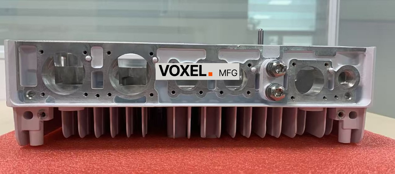
Machined interface condition on the finished heat sink after process stabilization
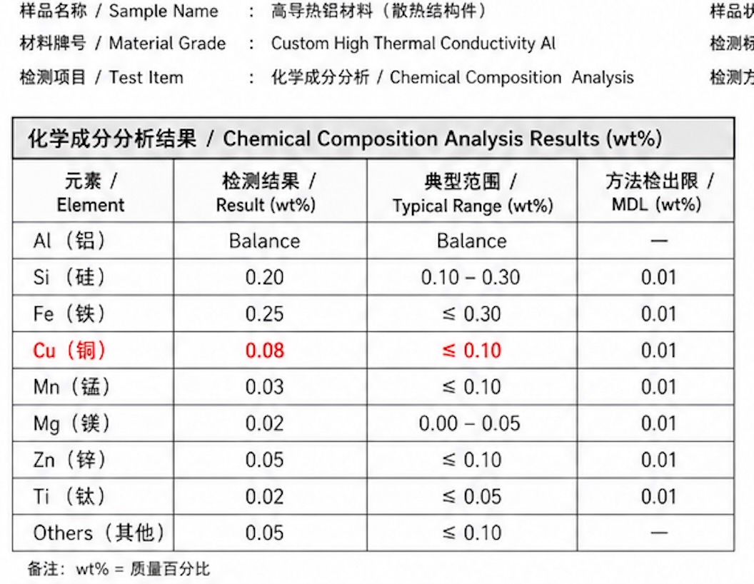
Spectroscopy analysis confirming copper content at 0.08% Wt, meeting the ≤0.10% material compliance requirement

IP67 leak test setup validating sealed enclosure integrity under pressure
What the Client Said
"We had four hard targets in the spec: thermal, sealing, salt-spray, and material compliance with a copper limit. Our regular supplier could cast the blank but had no answer for the downstream requirements. VOXEL's first trial confirmed the boundary with standard process, second trial narrowed it with gating changes, third trial added vacuum and mold temp control plus alloy adjustment. They understood that coating thickness is a compromise between salt-spray and EMC. One team, four targets, all met."
— Thermal Design Engineer, Telecom Equipment Manufacturer
Business Outcome
180 W/m·K
Thermal target exceeded, original design preserved
4-6 weeks
Schedule saved by avoiding full heatsink redesign
Zero tooling rework
Original tooling investment preserved
3 iterations
Converged process window for thermal, sealing, surface, compliance
Engineering Takeaway
When a spec sheet combines thermal performance, sealing density, surface durability, and material compliance — each with narrow windows and trade-offs — the problem is not any single requirement. It is the integration: knowing that coating thickness affects both salt-spray and EMC, that vacuum affects both fill and sealing, that alloy composition affects both thermal conductivity and corrosion resistance. VOXEL's value is not solving one requirement well. It is understanding how the requirements interact, and optimizing the full chain — blank, surface, and assembly — as one system.
Explore more engineering case studies on our Case Studies page.
Frequently Asked Questions
Why is high thermal conductivity aluminum harder to die cast into thin fins?
High thermal conductivity aluminum transfers heat into the mold faster than conventional die-casting alloys. In very thin fin sections, that rapid heat loss can freeze the melt before the cavity is fully filled, creating cold shuts and porosity unless the gating, vacuum, and mold temperature are tightly controlled.
What makes a 60:1 fin aspect ratio difficult for 5G RRU heat sinks?
A 60:1 aspect ratio means the fin cavity is extremely deep relative to its thickness. Molten aluminum must travel through long, narrow channels with almost no thermal margin, so any loss in flow speed or temperature can stop the fill before the part reaches full depth.
Why were vacuum die casting and constant mold temperature control both required?
Vacuum die casting reduces trapped gas and back-pressure in deep cavities, while constant mold temperature control preserves enough fluidity for the high-TC alloy to fill the fin channels. Using only one of these measures would not have been enough to stabilize this geometry.
How was thermal performance verified after the process changes?
After the gating and process updates were implemented, the finished parts were checked against the thermal target rather than judged by appearance alone. The alloy achieved a verified thermal conductivity of 180 W/m·K, exceeding the customer's target of 170 W/m·K.