IP67 Enclosure Case Study: Eliminating Leakage Paths Caused by Die-Cast Porosity
A European outdoor equipment manufacturer was producing ruggedized enclosures for industrial IoT deployments. IP67 sealing was a hard requirement — without it, the product could not ship. After tooling release, roughly 10% of units failed air-tightness testing. The failure rate sounds low, but the cost was enormous: leakage was only discovered after full assembly, calibration, and testing — by then, the entire unit had to be scrapped. VOXEL traced the root cause to tiny sand holes penetrating between the mounting hole and the shielding gasket groove on the cavity installation surface — they were so close together that even micro-porosity could create a leakage path. Using Moldflow simulation, runner redesign, and shot sleeve optimization, we eliminated the porosity at the source and brought the failure rate to zero.
Before
~10% of units failed IP67 air-tightness after full assembly — each failure meant scrapping the entire finished product, making the real cost far higher than the failure rate suggests.
After
Moldflow-guided runner and shot-sleeve optimization eliminated sand-hole porosity between the mounting hole and gasket groove — zero leakage after tooling fix.
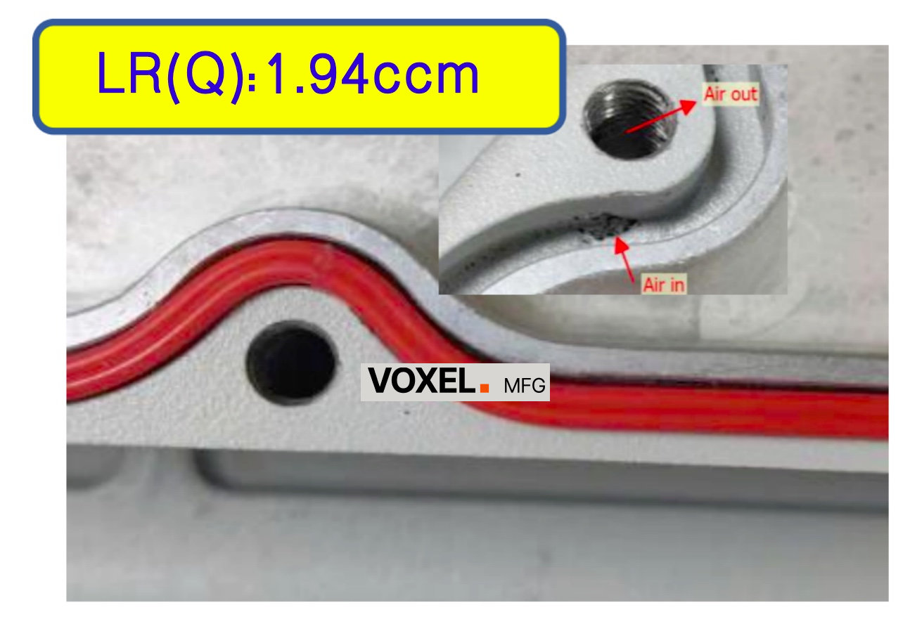
The critical zone: sealing groove and mounting hole proximity in an IP67 aluminum die-cast enclosure
The Problem: ~10% Failure Rate, 100% Scrap Cost
The customer was a European industrial equipment manufacturer producing ruggedized enclosures for outdoor IoT deployments. IP67 sealing was non-negotiable — their customers required it for field deployment in harsh environments. After tooling release, roughly 10% of units failed air-tightness testing. The failure rate sounds manageable on paper, but the real cost was enormous: leakage was only discovered after full assembly, calibration, and functional testing. By that point, the entire finished product — enclosure, electronics, labor — had to be scrapped.
The team did what any experienced engineer would do first: they systematically eliminated the obvious sealing variables. Gasket material — swapped and retested. Bolt torque — verified with calibrated drivers. Surface roughness — measured and within spec. All checked out. The leakage had to be traveling through the aluminum itself.
On the cavity installation surface, the mounting hole and the shielding gasket groove were located very close together — separated by only millimeters of cast wall. When tiny sand holes (micro-porosity) formed in this narrow zone during solidification, they could penetrate through the wall between the two features, creating a hidden leakage path that bypassed the gasket entirely. Most sand holes were too small to see — the vast majority of cavities looked perfectly fine to the naked eye. The root cause was only discovered when the team happened to find a cavity where the sand holes were large enough to be visible, confirming that porosity in this zone was the culprit. The question then became: how do you eliminate porosity you can't even see in a zone you can't inspect?
Why It Was Hard: Invisible Defects, Uninspectable Zone
The customer had not missed something obvious. The defect was invisible — the sand holes were too small for visual inspection in most units. 90% of cavities passed air-tightness testing because the porosity in that zone did not always create a continuous path between the mounting hole and the gasket groove. Only when the porosity happened to align through the wall did the part leak. This statistical nature made root-cause analysis far harder than a consistent, repeatable failure.
The business pressure compounded the technical challenge. Each scrapped unit represented the full cost of a finished product — not just a bare casting. At ~10% failure rate, the scrap cost was accumulating fast. The team could not simply increase inspection intensity, because the defect was invisible in most cases. They could not add a secondary sealant, because the leakage path was internal and inaccessible. And they could not redesign the part to move the features further apart, because the installation layout was fixed by the customer's system design. The only viable path was to eliminate the porosity at the source — which required proving where the gas was getting trapped, then changing the casting process to prevent it.
We ran Moldflow in two rounds. The first identified the general area of air entrapment near the sealing wall. The second confirmed the root cause: the runner geometry and undersized shot sleeve were creating a combined effect that folded gas into the wall between the mounting hole and the gasket groove. Neither factor alone caused the defect — their interaction did.

Moldflow simulation visualization: identifying air entrapment zones and optimized runner geometry
Engineering Actions: Change the Fill Pattern, Then Stabilize the Injection Window
The customer's hypothesis gave us a clear direction — simulation turned that direction into a plan. Moldflow confirmed it and revealed two factors had to be corrected simultaneously — changing either one alone would not eliminate the porosity:
- Runner geometry redesign: We lengthened the runners and adjusted their section to redirect the melt front, pushing gas toward the overflows.
- Shot sleeve correction: We increased the diameter from 100 mm to 120 mm to reduce early-injection turbulence. Without this, the runner fix alone would still have allowed air into the melt.
Verification and Results: Zero Leakage After Tooling Fix
After the changes, Moldflow predicted a clean fill in the critical zone between the mounting hole and the gasket groove. The T1 trial matched the simulation. The customer's team joined us for cross-section verification — they saw firsthand that the porosity was gone. After CNC machining, the enclosures passed air-tightness testing with zero leakage. The ~10% failure rate dropped to zero.
No redesign or sealant needed. No need to move the mounting hole or gasket groove. The failure was solved at the tooling level, where the root cause existed — by eliminating the sand-hole porosity that was penetrating between them.
Engineering Takeaway
When all sealing variables check out but IP67 still fails intermittently, the next step should be a Moldflow simulation of casting density in the zone between the mounting hole and the gasket groove. The customer found the root cause on a cavity where sand holes were visible — but most units had invisible porosity in the same zone. Simulation confirmed the pattern and revealed the process fix. The diagnostic approach: systematic sealing checks first, then find a visible defect to confirm the hypothesis, then simulation to prove and fix it.
What the Client Said
"The ~10% failure rate didn't sound alarming at first, but each failure meant scrapping a fully assembled and tested unit — the real cost was far higher than the percentage suggests. We found the root cause on a cavity where the sand holes were large enough to see, but most units had invisible porosity in the same zone. Once we knew what to look for, VOXEL ran the Moldflow and confirmed exactly where the gas was getting trapped between the mounting hole and the gasket groove. Fixed it at the source — no redesign needed."
— Structural Engineer, Outdoor Hardware Manufacturer
Business Outcome
~10% → 0%
Air leakage failure rate in critical zone — each failure previously meant scrapping a fully assembled unit
2-3 weeks
Schedule saved by finding root cause in one cycle instead of repeated trial-and-error
$5K-10K
Finished-product scrap costs eliminated — each scrapped unit cost far more than a bare casting
Moldflow
Root cause confirmed via simulation — visible sand holes on one cavity confirmed the hypothesis, simulation proved the pattern
Explore more engineering case studies on our Case Studies page.
Frequently Asked Questions
What is the IP67 waterproof rating and how is it tested?
IP67 is an Ingress Protection rating where '6' means complete dust protection and '7' means protection against temporary immersion in water up to 1 meter for 30 minutes. Testing involves pressurized air-tightness tests (typically 0.5-1.0 bar) to detect any leakage through the enclosure before water immersion testing.
Why does internal porosity cause IP67 air leakage in die-cast enclosures?
Internal porosity creates microscopic tunnels through the solid metal. When a sealing groove and mounting hole are located close together, pressurized air can bypass the gasket by traveling through these porous channels from the groove to the hole, causing test failure even with proper gasket and surface finish.
How does Moldflow simulation identify air entrapment in die-casting?
Moldflow simulates the molten metal flow during injection, tracking how metal fronts advance and where they collide. When flow fronts meet and trap gases before reaching vents, the software highlights these air entrapment zones, allowing engineers to redesign runners or adjust process parameters to eliminate porosity in critical sealing areas.
How does shot sleeve diameter affect die-casting quality and air entrapment?
Shot sleeve diameter determines the fill ratio in the cold chamber. An undersized sleeve creates excessive turbulence during plunger acceleration, folding air into the molten aluminum. By increasing the shot sleeve diameter from 100mm to 120mm, we achieved better control over plunger stroke dynamics, reducing air entrapment and improving casting density.